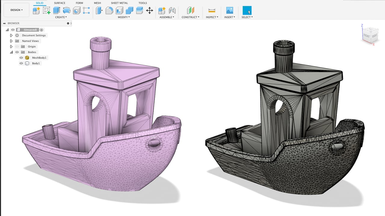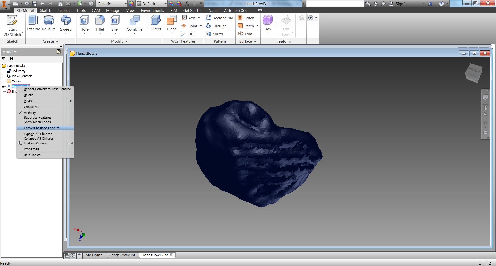

Convert the images from PNG to JPG (I used Irfanview Batch Convert) Load into Recap Photo, make new Object project, spend 12 cloud credits and start the mesh creation.
#HOW TO EDIT STL WITH MESH ENABLER PDF#

These techniques apply to basic CAD programs such as AutoCAD, IntelliCAD, etc. 5 in both the x– and y directions, and from about -0. For Input Features, select the polygon layer from Reverse route. The default is on.How to convert google map to autocad Route Simplification. Turns on or off the creation of the log file. You can change the name by editing the value to the right of the equal (=) sign. The available values for the format are: 0=Binary, 1=ASCII. Stores the surface plane angle value in radians. The unit value can be Inch or Millimeter. Turns on or off the creation of a base feature. The unit value can be Inch, Millimeter, or Meter. The following is a list of parameters found in the SESTL.ini file. Errors made to this file can adversely affect the quality of the translation. However, if you edit this file, use extreme caution in setting these parameters.

You can use a text editor, such as notepad, to set these parameters. When you make a change to a parameter in the dialog box, a new value is saved to the SESTL.ini file. The SESTL.ini file, found in the Solid Edge Program folder, is used to store the settings defined on the STL Import Options and STL Export Options dialog boxes. You can check for interference between facet bodies in a Solid Edge assembly document. When the Solid Edge part file contains a facet body, any commands that only add or removes material from the base feature are disabled.Ĭommands that calculate physical properties are supported for facet bodies in a Solid Edge part document. For example, when drawing a sketch, the Sketch command will not locate faces, edge, and vertices of a faceted body. You can only locate the entire body.Ĭommands that require faces, edges, or vertices as input will simply fail when trying to locate the faces, vertices or edges of a faceted body. You cannot locate faces, edges, or vertices of a faceted body. The Insert Part Copy command does not support. When you import a facet body, all faces are merged into a single part copy and represented by a single entry in Feature PathFinder. Even placed as a base feature, it is not considered a design body since no material can be added or removed from this type of feature. To place the facet body as a base feature, select the Make Base Feature option on the STL Import Options dialog box. When you import a facet body, it can be placed as a construction or as a base feature. However, since the facet part copy is a non-Parasolid body, the rules are different than those for a normal part copy. The facet body is displayed in Feature PathFinder as a part copy. stl facet body, it is stored in Solid Edge as a non-Parasolid body.


 0 kommentar(er)
